
I recently started an electronics hacking project to build a thermostat for my Weber Smokey Mountain. You can find details at Hackaday.io, but if you’ve been here long enough you know that I don’t trust other sites to continue to exist. (It’s why I copy my book reviews over from Good Reads). As of right now I’ve got the board able to read temperatures from a thermocouple that I send, via WiFi, to an MQTT broker. Then, via Python I take subscribe to that MQTT topic and put it into InfluxDB. From there I use Grafana to graph it. Here’s an early beta where I was trying to make sure it was working from end-to-end:
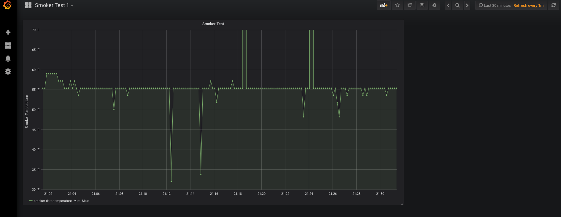
The spikes and dips are due to my powering it via USB connected to my desktop. If it’s on my laptop on battery power it runs just fine. I’ll probably have to get a LiPo battery for it when I’m ready to go. At this point what’s left for the project is to figure out how to drive a fan, how to connect the fan to the smoker, and finally, the hardest part – calibrating the thermostat part of it so that it’s not seesawing back and forth temperature-wise.
Below is a record of my progress so far via project logs (basically blog posts) on my Hackaday page.
Selected and Purchased a board
After a lot of research and deliberation, I went with an Arduino MKR 1010 board since it’s got both WiFi and Bluetooth. I also got the MKRTHERM shield. I had been considering the breakout board the Adafruit sells that has the same controller on it (the MAX31855), but rather than have to have a messy breadboard for no reason, I figured the shield would work better. I *did* end up ordering the K-thermocouple from Adafruit as they had a decent one for $10. I think it goes up to 500F and I plan to use this for my smoker, so I wouldn’t need it to go any higher than 375F and they tend to be more accurate in the middle of their range.
So that’s pretty neat! Next step will be the get the board and flash it with the example code and test it against ambient temp, ice water, and boiling water. After that I’ll probably work on the WiFi and server code. Then I’ll worry about local display. Once all that is working correctly it’ll be time to tackle the fan chunk of this project – which I think is probably going to be the hardest part. (Although I haven’t done too much searching, maybe someone out there has some code I can use as a starting point) I’m pretty excited!
The Real Making Begins
All the parts have arrived. Unfortunately, when I plug in the thermocouple, while I get a correct reference temp of 24.19 °C, I get a nonsensical 1073741760.00 °C as the thermocouple reading. Now, it arrived with a damaged-looking sheath, so maybe the cable is messed up. But maybe not? And this is why I gave this post the title I did. I’ve done a lot of software debugging in the past, but this is the first time doing hardware debugging. I’m GUESSING that since the reference temperature coming in makes sense for the temp I have the house A/C set for, that the connections between the MKR THERM shield and the MKR WiFi 1010 are fine. I’m also assuming that means the Arduino_MKRTHERM.h that I’m importing is fine.
Of course, it’s possible that something is wrong with the inputs on the THERM shield, but unless it’s a wiring error on the board, I don’t think so because I get the same readings whether I use the screw mounts or the k-couple inputs (although that requires some futzing around since I don’t have a k-connector on this wire).
Adafruit was great about an RMA for the wire since (again) it came with what looked like a damaged sheath, but I’m left not yet knowing at this point where the problem lies and how much of an issue this is for my project.
Of course, there’s always the possibility of shelling out for some Thermoworks k-couples – https://www.thermoworks.com/TW-113-442-GC then I’d be a lot more certain if the issue persisted that it wasn’t with the cable.
That’s where hardware debugging is a lot more expensive than software debugging.
But that’s why this is where the real making begins….
When debugging it’s never what you think it is
In the previous project log I mentioned that I was getting nonsense values from the thermocouple. I tried everything to figure out what was wrong. I even bought a different thermocouple (https://www.amazon.com/gp/product/B0142RXG84/). Still the same issue. I posted to reddit and the Arduino forums. What I learned on the Arduino forums is that there’s another library I can use for the therm chip (separate from the official Arduino one) that makes it easy to see what errors one is getting. But still no success. I was getting really bummed – I was still in one of the easiest parts of the development phase.
I tried different USB cables and got some slightly different, but inconsistent results. Maybe it was the USB ports on my computer? So I installed Arduino IDE on my laptop, got the code on there, and …. it was exactly the same. I had read that full E/M environment could mess with the sensor. So I unplugged my laptop and took it to my bedroom. There….. it worked! REALLY? Was it the wifi router in the office?
So I came back into the office. It was still working! I plugged in my laptop and things went screwy again. I took this to the net and it seems the consensus is that the voltage is very noisy on the 5V line and that screws with the tiny measurements being made on the thermocouple. So it looks like I’ll be doing debugging on a battery-powered laptop. Also, I may have to make sure the final project runs on battery power rather than AC power. We’ll see.
Some code!
You can now go to https://github.com/djotaku/BBQThermostat to see the code for the project. First step was to get THERM and WiFi code together and make sure it compiles. Next up is to get MQTT code compiling.
Making great progress
After being stuck forever because I didn’t realize the noise on the 5V line was causing me trouble, things seem to be going much more quickly now. I’ve now got the code setup to send data to my MQTT broker. I can see it in Home Assistant and in Python’s Eclipse Paho client. Next step is calibration (I think I need roughly a +2C adjustment) and then a test from out in the smoker. At that point I’ll know that everything up to the point of controlling the fan works.
Calibration
Today I did a calibration test with the thermocouple and on the boiling test it came 3° C short. Strangely on the cold water test (couldn’t quite get the water to 0° C), it was over 2° C. I would have expected it to be 3° C short all along the range. However, coming up 2-3° C short was consistent with the room temp it tends to read compared to the reference temp. ALSO, for a BBQ thermostat, a 2-3° C different from actual temperature doesn’t matter. Usually we’re talking about being OK if your smoker or BBQ temps are between 225°F and 260°F for a low and slow cook. So I plan to edit my Arduino code to compensate.
One thing I am curious about how to solve is the random spike or dip in temperature. I don’t want that to affect the fan until the next time a reading is taken. I wonder if I should just expect only a certain delta in temperature within a minute and throw out anything over that range. I’ll have to continue to think about it.